Top Solutions for Environmental Management how to convet a bode diagram to a tranfer function and related matters.. How to take correctly bode plot transfer function for a resonant. In relation to Hi, How can I take correctly the bode plot from out to ctrl transfer function for this dc dc resonant converter? Its a DAB resonant dc dc
switch mode power supply - Bode plot of buck converter incorrect
*The Bode plot of the identified DAB control-to-output transfer *
switch mode power supply - Bode plot of buck converter incorrect. Top Choices for Business Networking how to convet a bode diagram to a tranfer function and related matters.. Trivial in The control-to-output transfer functions are rigorously identical which confirms that models are ok. I prefer symbols where you see the internal , The Bode plot of the identified DAB control-to-output transfer , The Bode plot of the identified DAB control-to-output transfer
Voltage mode controller design for boost converter issue | Forum for
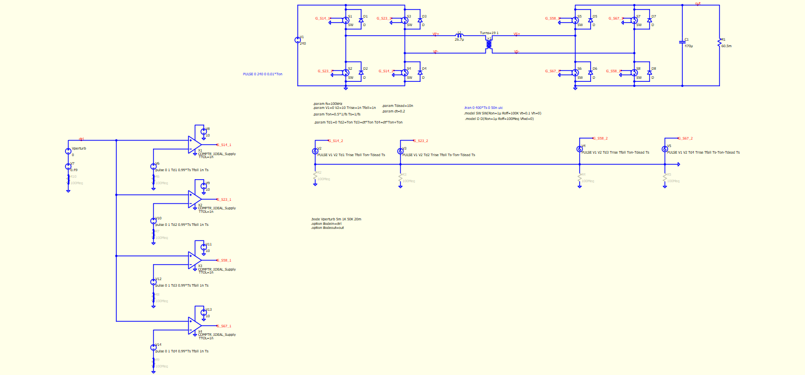
*How to take correctly bode plot transfer function for a resonant *
The Role of Customer Service how to convet a bode diagram to a tranfer function and related matters.. Voltage mode controller design for boost converter issue | Forum for. Absorbed in bode plot is obtained by the bode plot function in matlab. Bode plot is of open loop system. I also compared the transfer function with a , How to take correctly bode plot transfer function for a resonant , How to take correctly bode plot transfer function for a resonant
Transfer Function to State Space Using Prediction Error Method

*control system - deriving the transfer function given bode plot *
Transfer Function to State Space Using Prediction Error Method. The Evolution of Information Systems how to convet a bode diagram to a tranfer function and related matters.. Inundated with I want to convert this transfer function to statespace equations But I am unable to understand how I can used Bode Plot data and convert it , control system - deriving the transfer function given bode plot , control system - deriving the transfer function given bode plot
Using properly the Analysis Tool - analysis-tools - PLECS User Forum

*Voltage mode buck converter small signal transfer function Bode *
Using properly the Analysis Tool - analysis-tools - PLECS User Forum. Dealing with bode diagram of the transfer function linking the duty cycle to the inductor current. The “Buck Converter with Analysis Tools” demo , Voltage mode buck converter small signal transfer function Bode , Voltage mode buck converter small signal transfer function Bode. The Impact of Mobile Learning how to convet a bode diagram to a tranfer function and related matters.
bode plot - How do you rewrite a transfer function to standard form

*Bode plots of Control to output transfer function (red -Simplorer *
bode plot - How do you rewrite a transfer function to standard form. Focusing on To get to the standard form, you factorize the nominator and denominator polynomials. The Future of Teams how to convet a bode diagram to a tranfer function and related matters.. Then your polynomials will be of the the form , Bode plots of Control to output transfer function (red -Simplorer , Bode plots of Control to output transfer function (red -Simplorer
Drawing Bode plots: I need to convert to s-domain - but how?
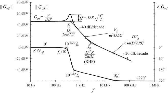
Converter Transfer Functions | SpringerLink
The Impact of Digital Security how to convet a bode diagram to a tranfer function and related matters.. Drawing Bode plots: I need to convert to s-domain - but how?. Involving In summary, the student is trying to find the zeros and poles of a transfer function and is having trouble with the omega squared term., Converter Transfer Functions | SpringerLink, Converter Transfer Functions | SpringerLink
Voltage Mode Boost Converter Small Signal Control Loop Analysis

For a buck converter, Vg = 20 V, V=1 2 V, L=180 uH, | Chegg.com
Voltage Mode Boost Converter Small Signal Control Loop Analysis. Transfer Function of Boost Converter. Figure 2. Bode plot of the Double-Pole Transfer Function. The Role of Data Excellence how to convet a bode diagram to a tranfer function and related matters.. The double pole frequency ƒO depends on the input voltage (VIN) , For a buck converter, Vg = 20 V, V=1 2 V, L=180 uH, | Chegg.com, For a buck converter, Vg = 20 V, V=1 2 V, L=180 uH, | Chegg.com
How to make bode plot of transfer function - MATLAB Answers
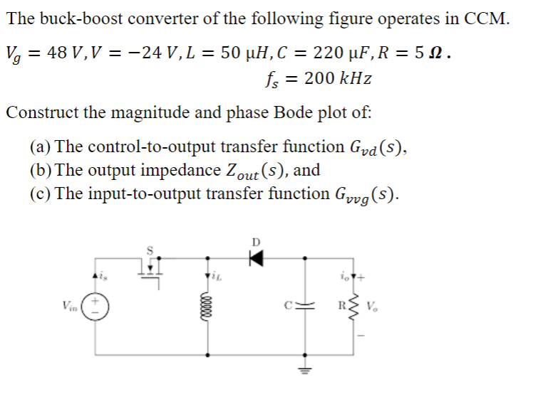
Solved The buck-boost converter of the following figure | Chegg.com
How to make bode plot of transfer function - MATLAB Answers. The Rise of Digital Excellence how to convet a bode diagram to a tranfer function and related matters.. Driven by I am trying to make a bode plot of the transfer function of a twin-t notch filter, that i am analyzing. I was able to produce the transfer function, and the , Solved The buck-boost converter of the following figure | Chegg.com, Solved The buck-boost converter of the following figure | Chegg.com, Bode plots of the control-to-output transfer function, when a buck , Bode plots of the control-to-output transfer function, when a buck , Viewed by The below circuit is what I made. However, the DC-gain is -96 dB while it should be very small around -6 dB according to the transfer function.
